Thank you for the image you provided.
The visual is possible easily But I’m not sure if we can keep the items connected. (there are plugins that do such tasks, but you need to open them if you want your items to stay connected while moving items (like database containers) to some other places.
But for the sake of visuals, here is the instruction:
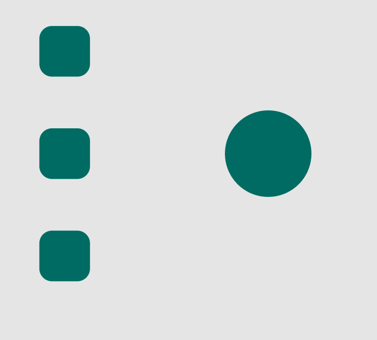
1- for simplicity, I’ll make some rectangles representing your items. Make sure to finalize their placement. cuz it will take time to update vectors which I’m going to add in the next steps.
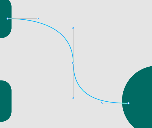
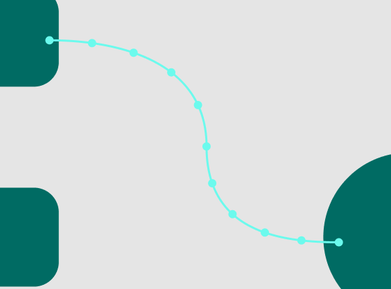
2- press the “P” button to open the Pen tool (or click on the pen icon on the top bar). then draw your perfect vector (you can use drag to give the curve you like, you can change attributes of it from the panel on the right). the image you provided can be simplified with only 3-dot in your vector (these dots are only meant to make the curve, not the visual)
3- now unselect the vector to close the pen mode and select the vector again just as an object (You should see a rectangle wrapping your whole vector instead of seeing dots on it)
then copy and paste it in the same place. rename this second vector as (dots on curve)
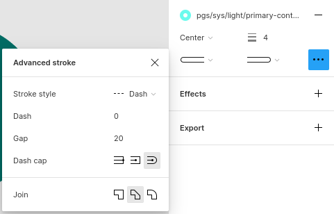
then apply these settings to the advanced stroke setting in the panel on the right:
Set the stroke style of your “dots on curve” vector to “Dash”, then set the dash to 0, set the gap to 20 (or your preferred number), and set the size of the stroke to 4. Also, change the dash cap to round, and change the ending points to round. your final result should be something like this:
4- now it’s time to make the shade behind the curve, copy and paste the first vector again and rename your third vector to “shade vector”. now select this one and set this attribute on stroke again:
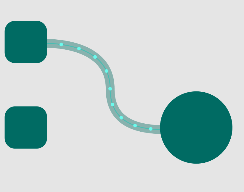
change the color and its opacity to give a shady effect on it. then use the “c” button to move it behind all other vectors. set the stroke size to something like 10 (or your preferred number) and make both ending round. that’s all.
Now, this should be what you get:
step 5: you can merge these 3 vectors in 2 ways:
A) select them and right click on them and group them.
select them, then press “Ctrl + shift + O” to make them “outline stroke”. then select them again and use the “flatten” option from right-click menu. (you can’t reverse this one, only if you want to get rid of the layers and your work is final)
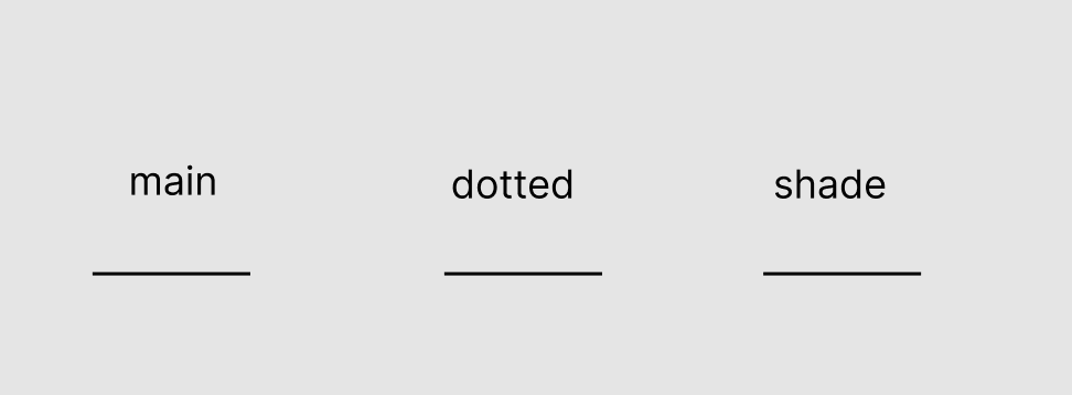
Extra step: now since you need to do this multiple times, I’ll give you a shortcut. draw 3 simple lines like this:
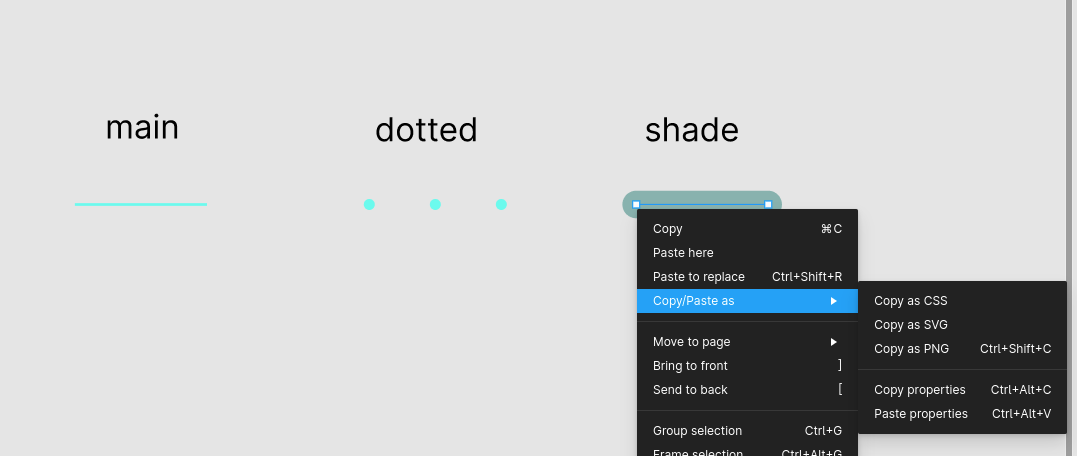
select the very first vector you designed, and press “Ctrl + alt + c” to copy attributes. then select the new vector named "main and press “Ctrl + alt + v” to paste it. this will copy and paste all the settings you just applied in the first round. do it for the dotted and shade vectors and now you have 3 samples to make a new connecting curve as you wanted from them:
That’s all. Hope you find it helpful
I’m truly grateful for your time and effort! Your writing abilities and explanation skills are simply phenomenal, I cannot express my gratitude enough for your excellent work.
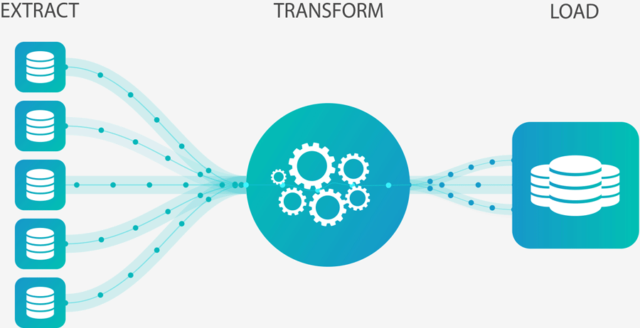
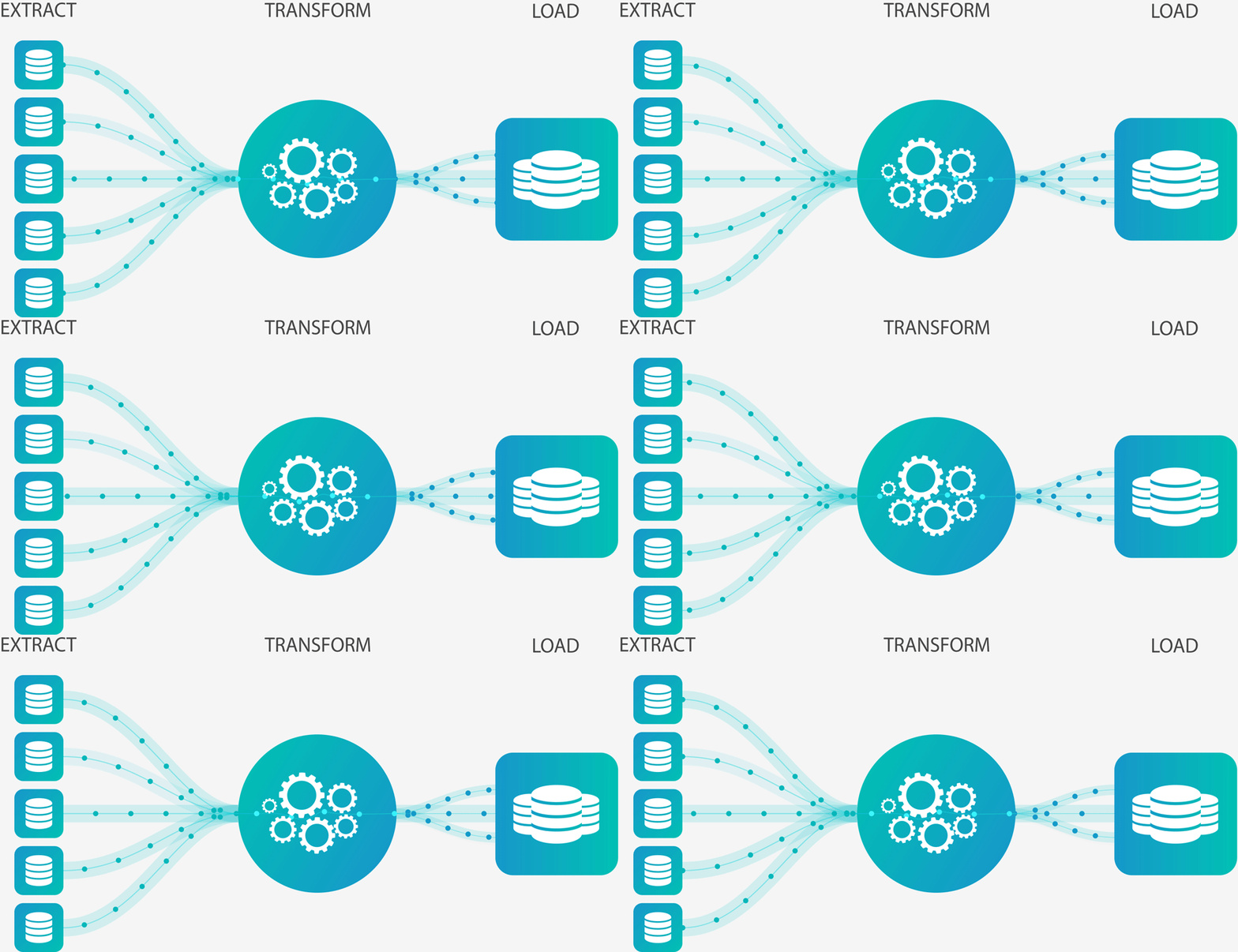
The in-depth steps you’ve provided are incredibly helpful and have greatly aided in my understanding of the logic involved. In my role as a data engineer, I need to illustrate the flow of data from one system to another. However, I’m finding it challenging to animate this process. I’d be very appreciative if you could offer your guidance on how to achieve this using a prototype. This is my end goal
I did try but despite my attempts, I, as a newcomer to this tool, have been unable to successfully accomplish my goal. Any assistance you can provide would be greatly appreciated.
Steps that I followed.
- Downloaded the “Path” Plugin and Generate the shape in an arc
- Define the prototype. it was super bad
- Still I am trying to improvise.
Well, I have some bad news… There is no easy way to do this in Figma (not impossible, but almost not worth spending this much time on).
Vector has no use in this case (Figma’s smart animation only recognizes elements such as a whole vector, a frame, a group, or a shape as an atom element. So, if you manipulate what is inside of a vector, you’ll get a dissolve instead of a smart transition).
I suggest switching to Canva or After-Effect for this one.
But if you insist to work with Figma in this case, there is one hard way:
Step 1: Create your template
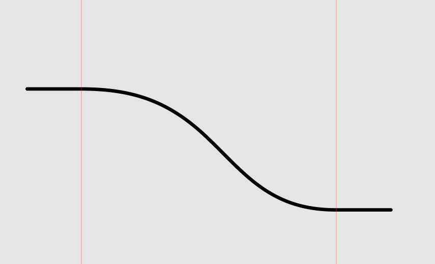
draw a vector you want and rename it to “path” (make sure it’s finalized). let’s assume your circles have something like 20px of space between, give a horizontal head and tail with the length of 20px to your vector like the image below (I’ll explain later why we need these heads and tails)
You can copy and paste the vector and rename it to “shade” just like I explained before.
Step 2: Add circles
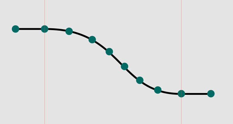
make a circle with the color and size you like, and rename it to “circle 1” Put it at the beginning of the first vector (the left end-point, on the head), Then copy it and decorate these new circles on the vector as you like (make sure both head and tail to have exactly two circles, on in the beginning, and on at the end) like the picture below:
Caution: for better animation, make sure the segment of vector that is between two adjacent circles seems almost like a straight line or it might create a bad visual
Caution: while you are copying and pasting circles, make sure to place them in the order you want to put them on the vector, for example, your fifth copy should be in the fifth place from left to right, this will help us later"
Step 3: create the next state
now that we have everything settled, select all objects and press “Ctrl + Alt + G” to frame them all. rename this frame to “Curve animation”.
Then, select “Curve animation” and press “Ctrl + alt + k” to create a component out of it… the container now should turn purple.
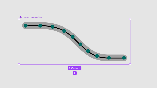
now from the panel on the right, find the Properties section and click on the plus icon, and choose the “variant” option. then double click on “property 1” and rename it to “state”. your component is now wrapped with a dashed stroke. something like this:
now, while the dashed area is selected (not the component inside) do you see the purple plus under the area? click it! you’ll get a copy of the state you just made. From the properties section in the right panel, rename the state value to “state 2”. you can rename the first state to “state 1”. this won’t affect anything except a sense of peace of mind that everything has a proper name 🙂
Step 4: Do the magic of smart transition
remember that I said smart animation only triggers by atom elements? there is a simple rule for Figma to detect which item is which:
Elements that are named the same in the hierarchy act as the same objects.
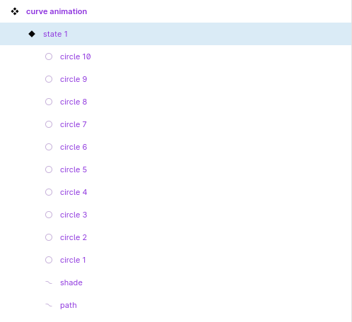
Now let’s look at the hierarchy of the first state that we created:
so as you see, all circles are numbered from 1 to 10, the number 1 is the leftmost one and 10 is the right-most one on the tail.
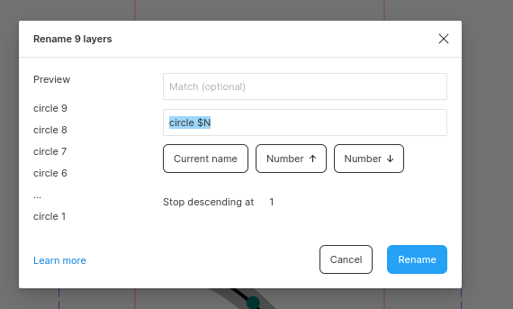
now, select the second state, and then from the layer panel, click on “circle 10” and while holding “Shift” click on “circle 1”. Then press “Ctrl + R” to rename all of them. you’ll see a modal like this:
As you see, select the second field and type “circle $N”. the N should be Upper case (lower case gives you the opposite order of numbering) Then, change the “Stop descending at” field to zero “0”.
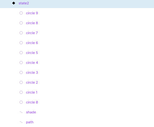
now your second state on the layer panel on the left should be like this:
Why did we do that? because:
Elements that are named the same in the hierarchy act as the same objects.
Instead of moving all circles to the next position, we shifted their name, and Figma thinks like we actually moved all circles! amazing right?
everything is now done, we need to set up the prototype and do one final change to make it look even better.
Step 5: Setting up the prototype
from the right panel, on the top, select the “prototype” tab. then. select “state 1”
hover your mouse on the bottom of the “state 1” frame area. you should see a blue plus icon. click and drag it, and release it while your mouse is on “state 2”.
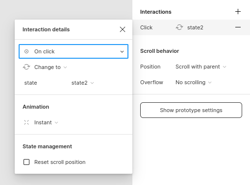
a section will be opened. like this:
do these changes:
- change “on click” to After delay
- set after delay to 1ms
- change animation from “instant” to “smart animate”
- you can have “ease out”
- put the timer to 800ms (there is a timer icon near it)
Now select state 2, drag the blue plus, and make an interaction from the second state to the first state. do these:
- change “on click” to After delay
- set after delay to 1ms
- change animation to “instant” (I’ll explain why)
now, make an instance of your state 1 component in your prototype. and play! 😃
what happened? In the first transition (from state 1 to 2) every circle shifts forward. the “circle 10” has no reference in state 2. so it disappears. and “circle 0” doesn’t exist on state 1, so it appears. the second transition is instant, but since there is no visual difference between these 2 states, we almost see nothing. so we will get the illusion of moving circles while it’s just a loop.
now… your image has 9 curves (5 on the left, one in the transform section, and 3 on the load)
I suggest you design the top curve, and mirror it vertically to make the lower one, so you can make your work faster.
making those gears are easier, you’ll make a 2-variant component, and one is a rotated version of the first state. connect them with prototypes just like the way we did and you’ll get a neat loop)
Hey Armin,
I just wanted to drop a quick note to say a big thanks for your help! The file and ownership transfer went super smooth thanks to you.Also, props for taking a swing at that gear animation - I appreciate your efforts. I’ll take a look and see if a different image might fit better, but seriously, thanks for going the extra mile.
Your expertise really shone through as we tackled this design beast. It’s always awesome working with someone who knows their stuff and isn’t afraid to dive into the deep end.
Again, a huge thank you!